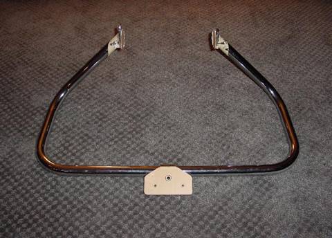
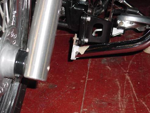
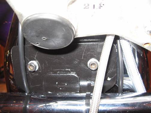
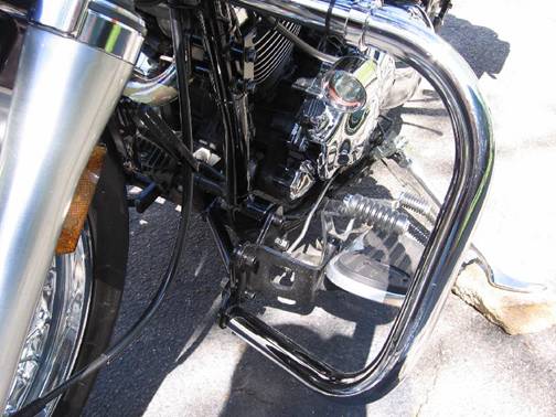
Picture # 9 – Orientation of Lower Mounts and Left Side Lower Mount Brace |
|
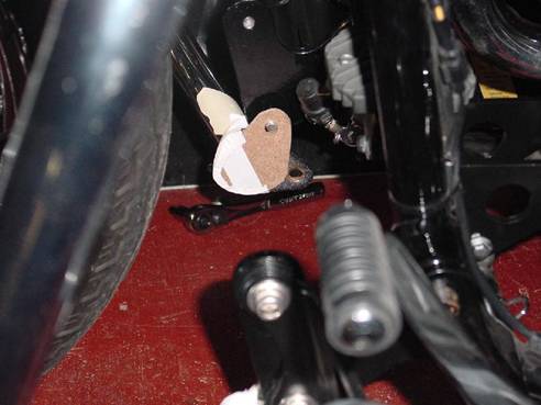
Picture # 10 – Another view of the left side |
|
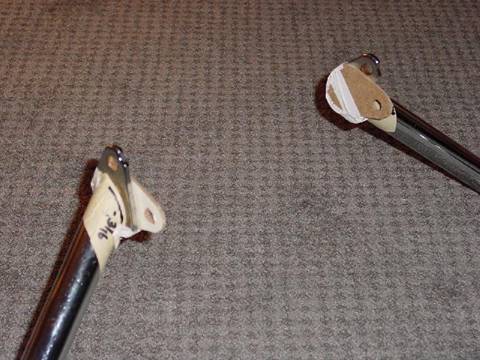
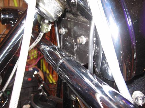
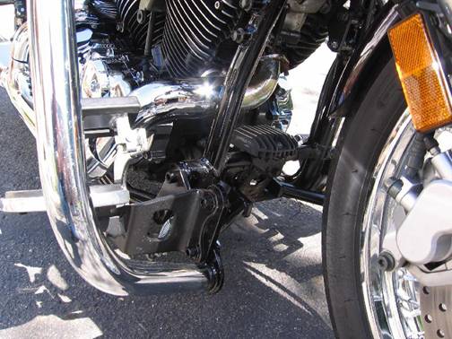
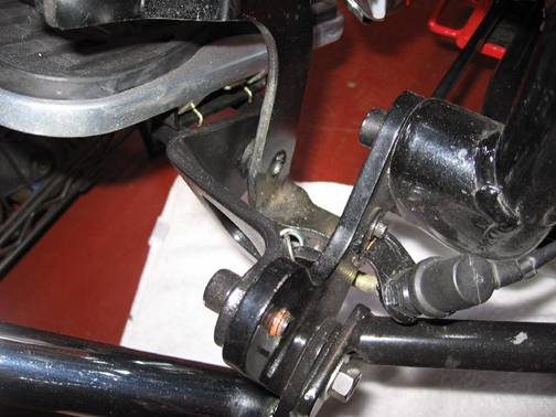
Picture # 11 – Orientation view of Right Side Lower Mount Bracket and Brace |
|
Picture # 11 – Orientation view of Right Side Lower Mount Bracket and Brace |
|
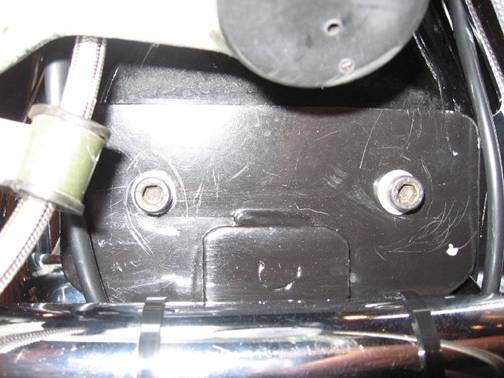
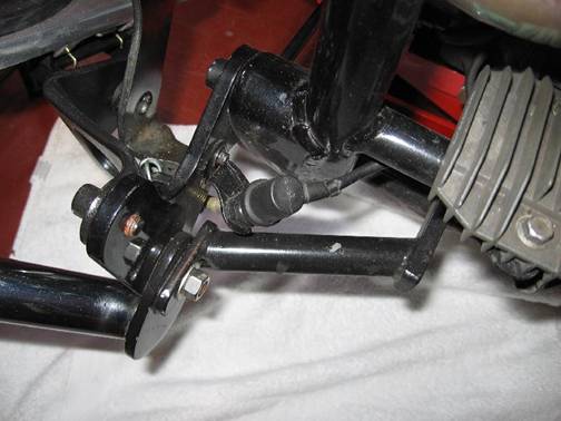
Picture # 13 – Another view |
 |
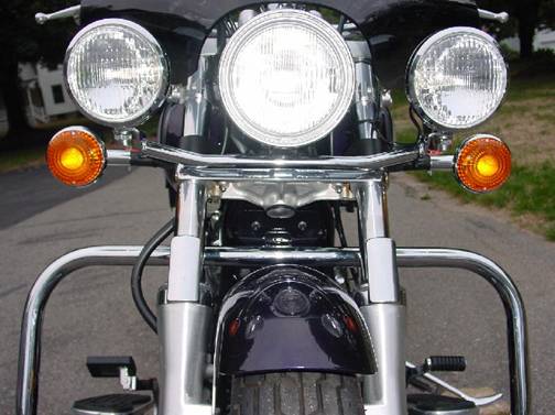
Picture # 14 – Relocated Stock Turn Signals and view of Upper Mounting Bracket |
|
Picture #14a – Close up view of Modification to Harley Top Bracket to utilize Front Neck Cover Bolts |
|
Picture #14b – A side view of the modified Top Mounting Bracket
|
|
Picture #14c – close up of Modified Front Bracket showing HD mounting tab welded to new Top Mounting Bracket. Neck Cover bolts are used to fasten the Mounting Bracket to the bike. |
|
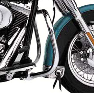
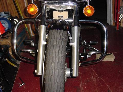
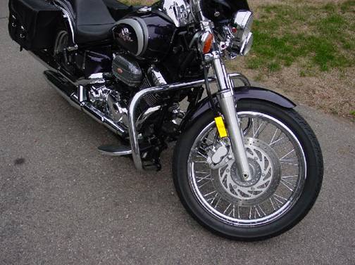
Picture # 15 – Another view - plenty of wheel clearance
|
|
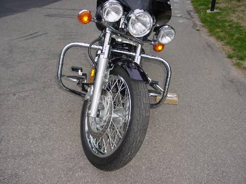
Picture # 16 – Turn Signals now clear the top of the Engine Guard. How about HD Engine Guard mounted Fog Lamps??? |
|
Picture #17 – 20 watt Halogen Spot Lights from JC Whitney attached to Engine Guard using Kuryakyn 1-1/4 inch “P” clamps and wired through a handle bar toggle switch. |
|
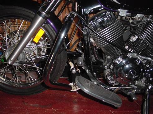
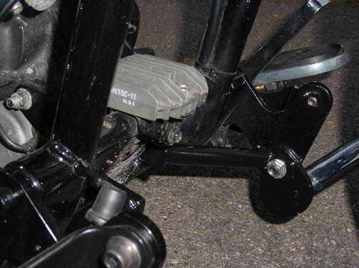
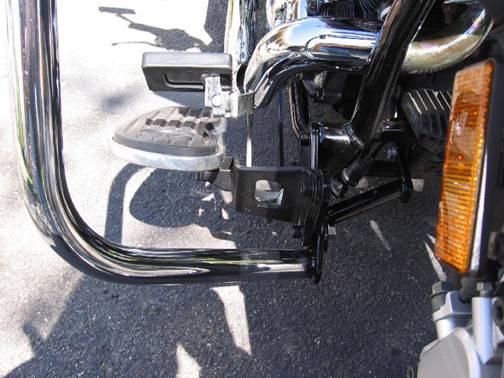
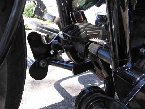
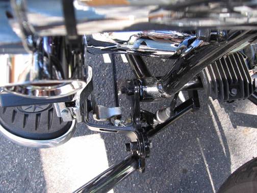
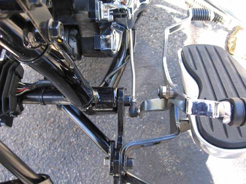
Picture #18 – View of Brake Foot Rest Assembly and Ziv’s Extension Brackets showing how everything lines up.
|
|
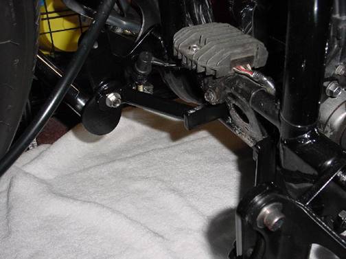
Picture #19 – View of the Shifter side showing Ziv’s Extension Brackets and Shifter Foot Rest assembly |
|
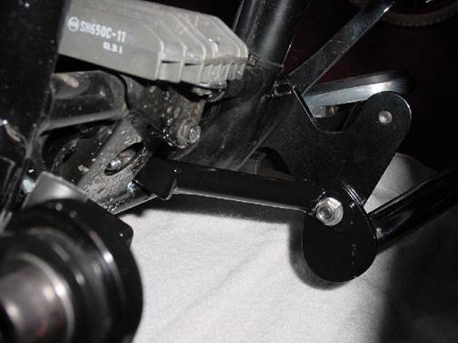
Picture #20 – Showing detail of Ziv’s Extension Brackets and the location of the Modified Engine Guard lower mounting bracket and its lower support brace |
|
Picture #21 – Another front-on view from the Brake side |
|
Picture #22 – Showing the detail of Ziv’s Extension Bracket on the left side and the Modified Engine Guard Lower Mount and its support bracing
|
|
Picture #23 – Showing close up detail of Ziv’s Extension Bracket, modified Engine Guard mount and its lower support bracing and the Shifter Foot Rest assembly |
|
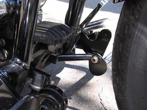
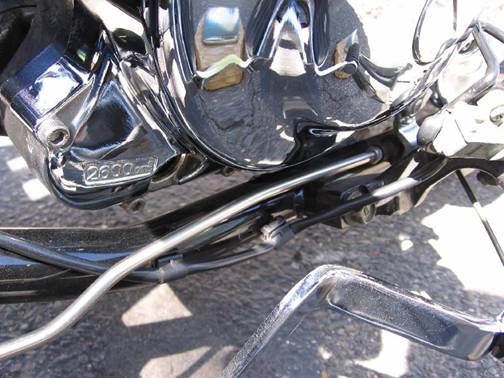
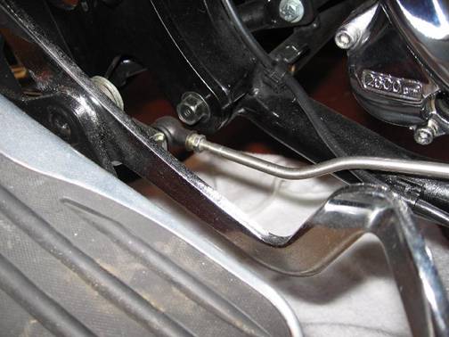
Picture 24 – “Bird’s Eye” view of the brake side showing detail of brake light switch and brake rod mounting.
|
|
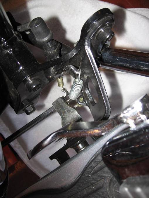
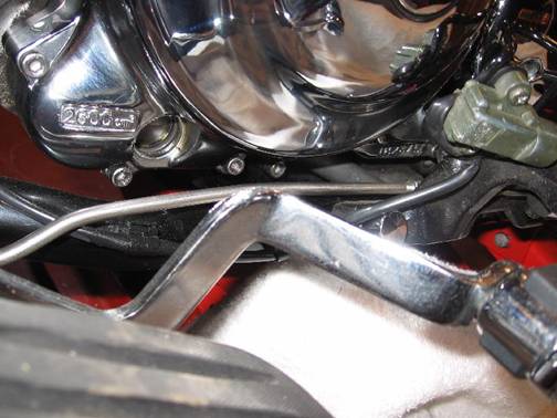
Picture #24a – A close up view of the Brake side spring connections |
|
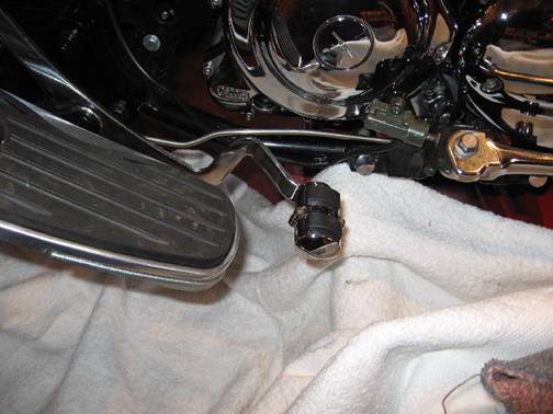
Picture #24b – View of Brake Light Switch |
|
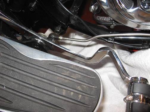
Picture #24c – Another view of the brake light switch as well as lower engine guard mount and lower support brace. |
|
Picture #25 – “Bird’s Eye” view of the shifter side set up. Note: the shift rod needed to be bent to clear the lower mounting bolt, sidestand mount and the frame |
|
Picture #26 – Shows how I had to bend the Shifter rod using Ziv’s Extension Brackets and Classic FootRests on a 650 Custom |
|
Picture #27 – Showing bend in the forward end of the Shift Rod to clear the Bottom Mount od Ziv’s Extension Bracket |
|
Picture #28 – Another view of the Shifter Rod bent to clear all obstructions |
|
Picture #28 – Another view |
|
Picture #29 – Another view |
|