|
AIR INDUCTION SYSTEM (AIS)
|
This system burns the unburned exhaust gases by injecting fresh air (secondary air) at the exhaust port. This is to reduce the output of the hydrocarbons. When there is negative pressure around the exhaust port, high vacuum on the intake side, during deceleration , the reed valve opens and the secondary air flows into the exhaust port. The required temperature for burning the unburned exhaust gases is approximately 600 degrees to 700 degrees. |
Disable |
This deals with the disabling of the AIS on the bike which is a re-burn system for pollution control. If you live in a state that does yearly emissions inspections you may want to just disable and then hook it up for the inspections. Disabling this will reduce the backfiring and pops from the exhaust on deceleration. |
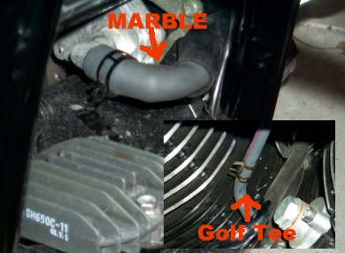
This is the location of the AIS canister and the place where the disable will take place. |
.jpg) |
|
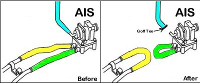 |
This is a diagram of the disable |
|
The blue hose on goes to the port on the intake manifold below the front carb. Just install a golf tee or something to plug the hose. The yellow line runs to the plumbing which goes to the cylinder jugs and you can install a marble anywhere in line. |
This is easy to reverse in case of emission inspections in your state. |
 |
|
Removal |
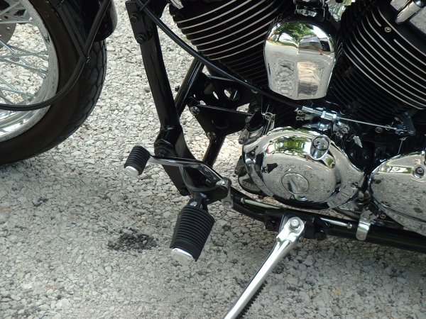 |
Removal of the AIS cleans up the look of the front end of the bike.
|
|
Step by Step |
-
Remove the shifter side forward controls for better access.
-
Remove the 3 allen head bolts holding the outside case of the canister.
-
Remove the 2 Phillips screws to the left of the inside unit. Tap on the end of your screw driver to loosen these up a bit before you attempt to turn them.
-
Remove the guts from the black canister.
-
Now you will have the empty canister housing. You will notice the three Phillips screws attaching the canister to the frame. These things were installed at the factory with a very good lock-tite. Save yourself the trouble and just use your Dremel and a fiberglass cut off wheel and cut off the heads of the screws. The housing will then slip right off the mounting screws.
-
Now you can just use your Dremel and a fiberglass cut off wheel and cut off the screws close to the frame. Then can use the Dremel to grind the leftover screw down flush and paint for a totally stealthy appearance.
-
You can also replace the motor mount with a right side mount for about $6.00 and even looks better.
-
Tubing Removal. Use a 6mm socket and extension to loosen the hose clamp on the front and rear cylinders where the tubing connects. Tap the hose with a screw driver and hammer to make sure it is loose.
-
Loosen all the allen head bolts in the engine cases and remove the brackets holding the tubing in place. Remove the clamps holding the vacuum hose that holds the tubing together and remove all tubing from the motor.
-
Finally, plug the holes in the spigots attached to the cylinder heads. Use Hi-Temp RTV applied to a 10mmx25 bolt. Allow the Hi- Temp RTV a 24 hour time period to completely cure. Replacing the spigots with after-market plugs, is hard to do on the 650 engine because of frame interference.
|