Re-jetting by "MGD" Jeff
Here are basic instructions for rejetting the carbs for a HyperCharger with free flowing pipes. If you're jetting for a different intake and/or exhaust combination, see the Jet Chart on the 650ccnd.com website. I started with the needle replacements on the right side of the bike.
(note) From the factory, the carbs come with brass screws. These are difficult to remove because they are JIS not Phillips. The screwdriver that comes with the bike, in the tool kit, is a JIS. If you do not have access to this, try making the Carb screw tool. This will make it easier to get the screws out.
 |
This shows a view from the top of the carbs looking down into the venturis. You can see the vacuum slides and needles. The tapered end of the needles fit into the needle jets in the wall of the carbs. |
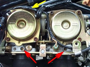 |
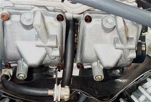
This shows a view of the right side of the carbs with the covers on. The clamp for the choke slide has already been removed and the choke cable is hanging free. |
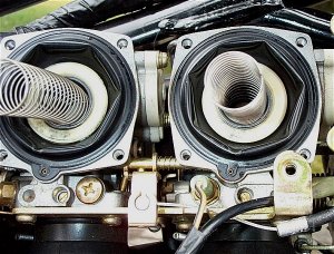 |
The covers have been removed and the vacuum slide assemblies with the slide springs are exposed. |
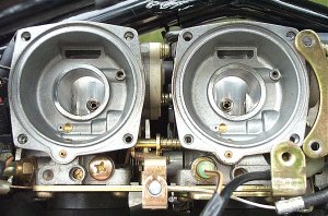 |
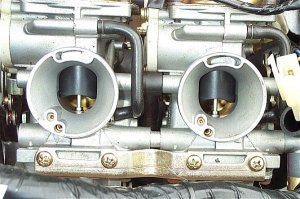
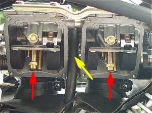
The slide assemblies have been removed. The needle jets can be seen protruding from the carb wall on the inside of the venturis. |
The pictures above, show a couple of views of the right side of the carburetors.
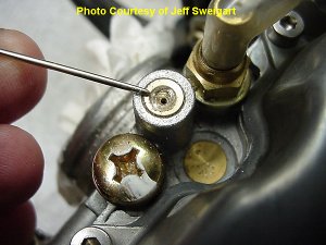
The yellow arrow in the picture above points to the wire harness for the carb heaters. I disconnected the wire harness at the connector located under the seat and moved the wires out of the way for easier access to the carb covers. The red arrows point to the idle mixture screws. I had already re-jetted the carbs previously for the RAK mod so the brass plugs had already been removed. Included in the jet kit are a drill bit and self tapping screw to remove the brass plugs. The idle mixture screws are recessed about 1/4". The drill bit is used to drill a pilot hole for the sheet metal screw through the top of the brass plug. You have to be careful to not let the bit penetrate too far and damage the idle mixture screw under the plug. Once the hole is drilled, the screw is threaded a few turns into the plug and a pair of pliers can be used to pull the plug from the carb body. The idle mixture screws should be turned in (clockwise) until they seat gently. Open each idle mixture screw 3 1/2 turns (counter clockwise).
The pictures below show the idle mixture plug and screw from an 1100 carb, but the process of removing the plug is the same for the 650.
 |
The pilot hole has been drilled in the plug. Note that the hole is just beginning to break through the plug, not drilled through the plug. You don't want to damage the idle mixture screw under the plug. |
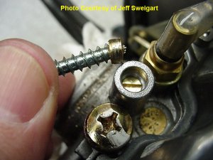 |
The self tapping screw has been threaded into the pilot hole that has been drilled in the plug. Use pliers to wiggle the screw and pull the plug out. |
As I mentioned, I had already re-jetted once, so the brass carb cover screws had been replaced with steel allen head bolts. The allen head bolts are a breeze to remove. The stock brass screws are very soft and can be a real chore, as the heads strip easily. Some have used a posi-drive bit very successfully to remove the brass screws. I originally removed the carbs from the bike to work on the screws. Some of the heads stripped as expected and I ended up cutting a single deep slot in the heads of the screws and using a large flat blade screw driver to remove them. Whatever you do, replace those blasted brass screws with allen head bolts! Stainless allen head bolts are the best but I couldn't find any at the time so I used plain steel. As you can see from the pictures, they rusted in no time at all. It doesn't hurt anything but they look like crap. I've got to get stainless!!
Once you carefully remove the cover plates, the vacuum slides are exposed with the slide springs. Remove the springs and carefully remove the slides by gently pulling on the diaphragm edges.
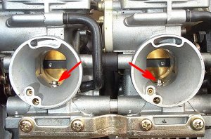
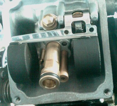
Another look down into the venturis with the slides and needles removed. The arrows point to the needle jets located on the venturi walls. |
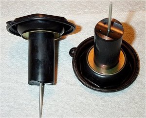
The vacuum slide and needle assemblies ready to be worked on.
|
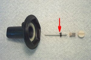 |
The vacuum slide assembly parts. The slide, needle with black spacer/seat, clip on the 5th groove, spacer washer, needle seat spring and needle cap. |
If you don't have adjustable needles, you can shim the needles by installing 2 # 4 washers between the black spacer/seat and the clip which shims the needle to about the top of the T on the needle itself. |
To disassemble the needle from the slide, remove the needle cap with a screw driver. Be sure to hold the vacuum slide by the plastic cylinder body and not the diaphragm. Handle the diaphragm as little as possible to avoid ripping or damaging it. Once the needle cap is removed, the needle and needle seat spring will fall out of the slide. Note the little nub on the black nylon spacer/seat, indicated by the red arrow in the picture above. This nub MUST fit in the tiny hole in the base of the vacuum slide when it's reassembled. In the picture above, the red arrows point out the needle jets on the venturi walls. The needle jets on my carbs stick out from the venturi walls about 1/16". On some carburetors, the jets may be flush with the venturi walls.
If you have adjustable needles, install the new circlip in the 5th groove if the jets protrude out from the venturi walls. Install the clips in the 4th groove if the needle jets are flush with the walls of the venturi. Remove the black spacer/seat from the old needle and push it onto the new needle, up against the circlip.
If you do not have adjustable needles, place the #4 washers in between the circlip and the black spacer (see picture above).
Place the needle seat spring on the top of the needle and insert the new assembly into the slide making sure the nub seats in the tiny hole in the base of the slide. (some people have removed the nub) Install the needle cap and tighten it firmly but not excessively. Make sure it's not cross threaded or over tightened!
Insert the slide assemblies back into the carbs being careful to align the diaphragms in their seats. Gently move the slides in and out a short distance to make sure that they are free moving. Place the springs back in the slides and put the covers back on. Remember,...do yourself a favor and replace those brass screws with 8, 4mm x 10mm allen heads,... stainless if you can get them! The bottom right hand screw on the rear carb is just in front of the choke slide. You may have to put a couple of washers on that bolt before installing it in the cover plate to keep the choke slide from binding on the shaft of the bolt. A 10mm bolt here, is a little long but it will work fine with a couple of washers. Reattach the carb heater wire harness and put the bracket back on the choke cable end. The needles are done!
Next page, on to the jets!
 |
The main jets are housed in the float bowls on the left side of the carbs. The idle speed adjustment knob/cable will have to be moved out of the way to get to the cover screws. |
 |
The float bowls house the main jets, pilot jets and floats. The carb vent hose is seen between the two carbs and is routed down through the heat shield between the cylinder jugs. |
Remove the covers here, just like the other side. The only difference here is that gas in the float bowls will drain out onto your bike. Be ready with a couple of rags to catch the gas as it leaks from the float bowls. Keep track of the placement of all the brackets and holders.
Once the covers are removed, you'll be able to see the main jets, indicated by the red arrows in the picture above. The main jet on each carb is located between the floats. Be careful not to hit the floats or bend the float adjustment tang. It can be a real bear getting the floats adjusted again if they become misaligned. The yellow arrow points out the carb vent hose. Make sure the vent hose remains intact and is not bent or kinked.
The main jet standoffs end in a hex head fitting that can be held with a small wrench while a screw driver is used to remove the jets. Install the new main jets. see note (1)
Replace the covers. Again, use the allen heads. Use 8, 4mm x 12mm bolts for these covers. Attach the idle speed adjustment to its bracket. Jets are done!
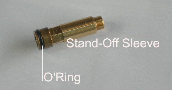
Note (1)-For '04 or later CA models, and all models 07 and later, remove the O-Ring from the standoff sleeve.
 |
 |